Bodytracking with webcam and Nvidia Body Chop
Category: Experimentation, Body Tracking
1. Introduction
This post explores body tracking in TouchDesigner using the NVIDIA Body Track CHOP. A feature exclusively available on windows computers. In which I was glad to have been provided the laptop from school. The end goal was twofold:
- Generate a 3D skeleton from video input for interactive purposes.
- Integrate the skeleton into an existing masking system, creating dynamic interaction between body movements and projected visuals.
This post is split into two parts:
- Generating the Skeleton: Using NVIDIA Body Track CHOP to generate accurate joint data and render a 3D skeleton.
- Connecting the Skeleton to the Masking System: Flatting out the 3D skeleton into a mask to mix into my previous masking setup and create a real-time dynamic mask.
2. Generating the 3D Skeleton
Objective
To process a recorded video of myself walking in front of a wall and waving (simulating user interaction) into joint data that renders a 3D skeleton.
Creating this 3D skeleton from the joint data required some advanced scripts and node structure I could never have found out myself. That’s why I followed along with the “Line skeleton creation” part from this video. But instead of using the joint data from the kinect, I used the data from the bodytrack chop.
If it would get too complicated following along with these steps for creating the skeleton; You can always watch the video instead.
Video Input
Detailed Steps
1. Preparing the Input Video
Movie File In TOP:- This operator loaded the pre-recorded video of me walking and waving. Using a recorded video allowed me to test body tracking without requiring live webcam input.
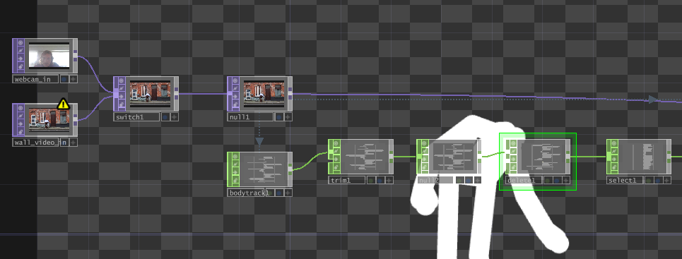
2. Connecting to NVIDIA Body Track CHOP
Body Track CHOP:- Connected the video file to the Body Track CHOP, which automatically detected the body and tracked its joints in real-time.
- Output: A comprehensive set of joint positions representing the skeleton structure, including:
- Major joints like head, shoulders, elbows, wrists, pelvis, knees, and ankles.
3. Refining the Joint Data
To enhance accuracy and usability, I had to process the raw joint data using the following CHOP operators:
Trim CHOP:
- Synchronized the timeline to ensure the video and tracking data matched frame by frame.
Shuffle CHOP:
- Reorganized the joint data into a format suitable for rendering as geometry. This step converted the data into rows/columns representing each joint’s X, Y, and Z positions.
Math CHOP:
- Scaled and normalized the joint coordinates for consistent visualization and ensured proper proportions across the 3D skeleton.
Node overview so far::
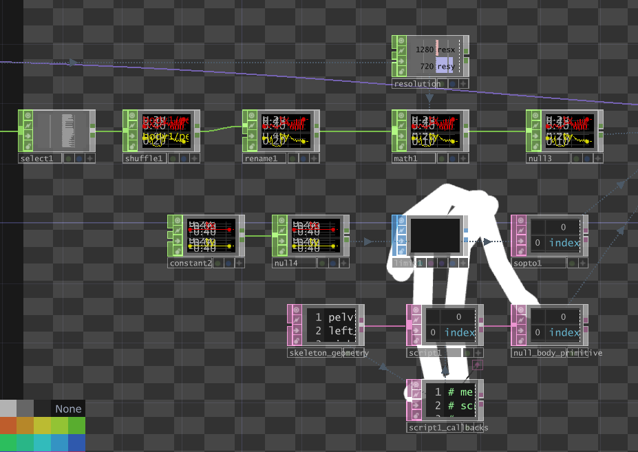
4. Input and Data Structuring
Select CHOP:
- This node is used to extract specific data streams from the incoming joint data provided by the Body Track CHOP. It isolates the data for individual joints (e.g., wrist, pelvis, or any specific tracked point).
Shuffle CHOP:
- The data is restructured here. The purpose of this step is to convert the data from sequential (per joint) into a more organized format (e.g., rows for X, Y, Z positions or vice versa), making it easier to process for rendering.
Rename CHOP:
- Joint data is relabeled here for clarity. For example, joint positions may be renamed to more descriptive names such as “left_wrist_x,” “right_wrist_y,” etc. This makes it easier to manage the data downstream.
5. Data Scaling and Normalization
This is where it gets really tricky. Because you have to retrieve some date from inside the Bodytrack CHOP. I would recommend following the video for the following steps.
Constant CHOP:
- Introduces fixed values that might be used to scale, normalize, or offset the positional data. These constants could, for instance, represent the 3D space’s bounds or the scaling factor for rendering.
Math CHOP:
- Performs mathematical operations (like scaling, adding offsets, or normalizing) on the data. In this case, it ensures the joint data is in the correct coordinate range for rendering. Scaling values to fit a 3D viewport.
Null CHOPs:
- Act as stable points to organize the network and output clean, finalized data streams. These ensure all transformations and operations are complete before passing the data forward.
Skeleton Geometry SOP:
- Converts the CHOP data into visual geometry:
- The joints (as points) are rendered in 3D space.
- The connections between joints (e.g., bones) are created as lines to visualize the skeleton.
Script CHOPs:
- Retrieved from the
Bodytrack CHOPcomponent.
Resolution CHOP:
-
Gets the original dimensions from the wall video to create the 3D scene accordingly
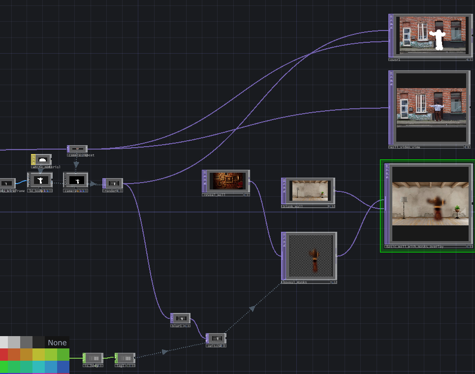
Node overview so far::
4. Creating the Skeleton
The processed joint data was fed into a SOP (Surface Operator) network to render the skeleton:
Skeleton Geometry SOP: Converts the CHOP data into visual geometry:- The joints (as points) are rendered in 3D space.
- The connections between joints (e.g., bones) are created as lines to visualize the skeleton.-
Render TOPandCamera: - Added to create a 3D scene for viewing the skeleton in real-time.
- Additional Enhancements:
- Added a light source to improve visibility and better visualize depth.
Nodes created::
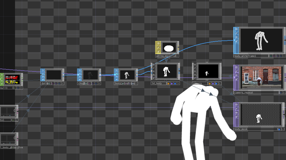
Final skeleton nodes overview::
final video:
Download the project file for the 3D skeleton
3. Integrating the Skeleton into the Masking Setup
Objective
The goal here was to transform the generated 3D skeleton into a 2D mask and integrate it into my masking system from previous posts. This would allow the skeleton’s movements to dynamically reveal or hide parts of a projection.
Detailed Steps
1. Flattening the Skeleton
Why Flatten?:
The masking system operates in 2D, so the 3D skeleton needed to be projected onto a 2D plane.
How?:
Scaled and adjusted the depth (Z-coordinate) using Math CHOP to create a flattened 2D version of the skeleton.
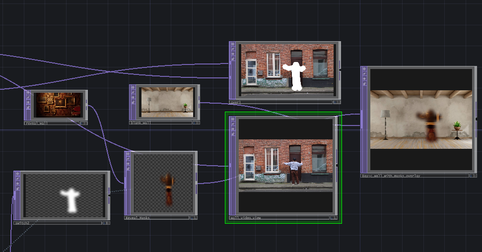
2. Integrating the Mask
- Composite Setup:
- Used the skeleton’s 2D output as an input to the Composite TOP, where it acted as the dynamic mask.
- Masking Layers:
- Foreground Layer: A hidden projection (e.g., a second room or alternate wall image).
- Background Layer: The primary room or wall image.
- Composite Operation: Used the skeleton as a mask to blend the two layers, revealing the hidden image wherever the skeleton was present.
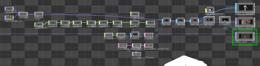
Connected mask overview:
3. Synchronizing the Output
- Merged the masked output with the original video for testing:
- Ensured the skeleton aligned with the original motion in the input video.
Focus on nodes:
4. Observations and Challenges
Insights
- The Body Track CHOP provided accurate and detailed joint tracking, which worked well for generating the skeleton.
- Integrating the skeleton into the masking system demonstrated the potential for real-time, interactive projection mapping.
Challenges
- Precision Issues:
- The skeleton’s mask was not precise enough for high-detail applications, leading to slight inaccuracies during interaction.
- Testing Without a Projector:
- Testing on a flat monitor limited insights into how the system would perform in real-world environments.
5. Results
Here’s a demonstration of the final output:
-
Generated Skeleton:
-
Masking System in Action:
6. Future Improvements
- Precision Enhancement:
- Explore alternative tracking solutions or refine the CHOP processing pipeline for more accurate mask generation.
- Real-world Testing:
- Integrate the system with a projector to evaluate its performance in real-world installations.
- Interactive Features:
- Add depth-based interactivity (e.g., hiding or revealing elements based on distance).
7. Resources
- Tutorial: watch the video instead
- Nodes Used:
Body Track CHOP,Trim CHOP,Shuffle CHOP,Skeleton Geometry SOP,Composite TOP,Script TOP, …